
ProGuard Tenant Storage
Choose The Right Locker Arrangement
Compare usable height, compartment count, and door access, then review the construction that makes up the system.
Single-Tier Or Double-Tier?
Both configurations use the same basic ProGuard construction. The difference is how the bay divides usable height and how many residents can be assigned separate compartments.
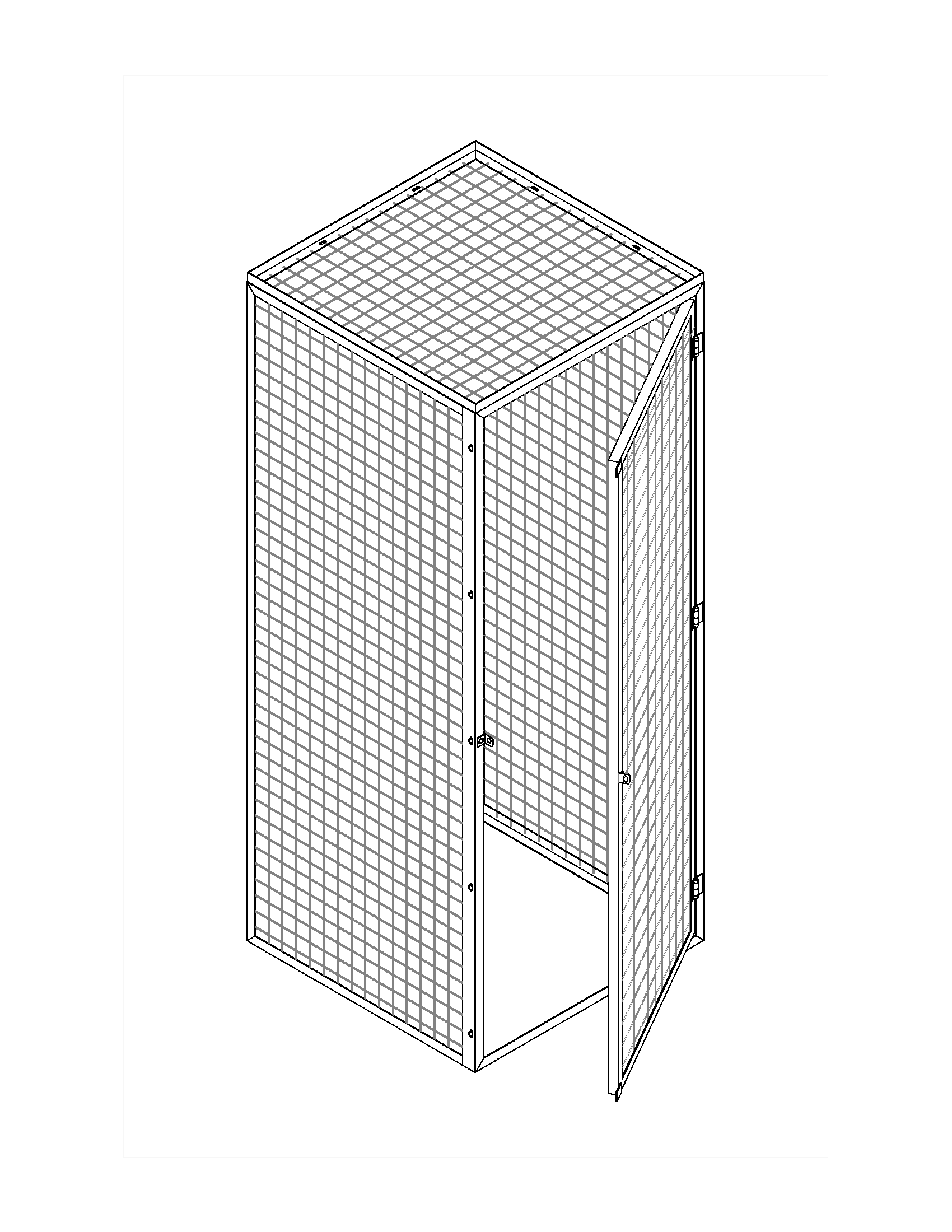
Doors closed
One Compartment Per Bay
Single-Tier Lockers
One full-height compartment with one door. A useful starting point for taller belongings and uninterrupted vertical storage.
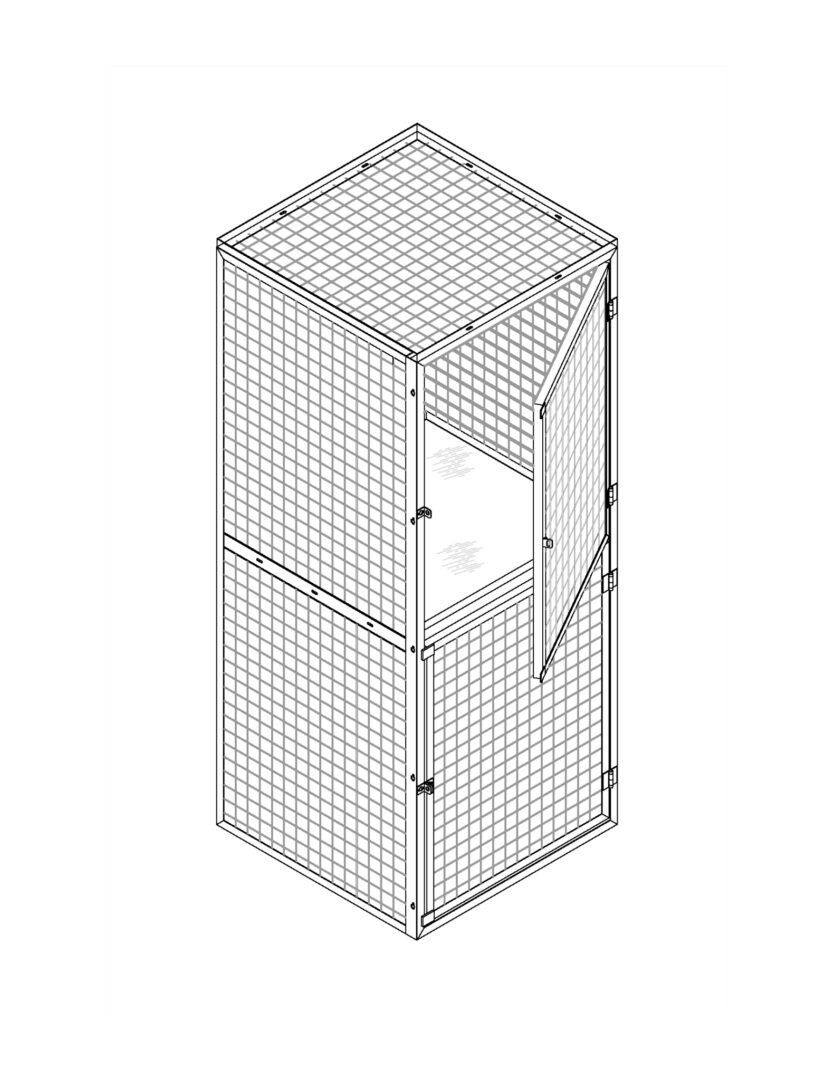
Doors closed
Two Compartments Per Bay
Double-Tier Lockers
Two separately accessed compartments. Check the reduced height and access to the upper compartment before choosing the count.
Think In Compartments And Bays
A bay is one position along the locker row. A single-tier bay provides one compartment; a double-tier bay provides two. For example, a row of six double-tier bays provides twelve separate compartments. The shared-divider and end-panel requirements still depend on the layout.
A Mixed Room Can Make Sense
Some residents need taller storage, while others need a smaller assigned space. A room can combine configurations and dimensions. Mark which compartments need more height, then review the doors, dividers, and aisle arrangement together.
Explore The Locker Construction In 3D
See the angle sections, overlapping round wires, shared dividers, hinges, and connection hardware as a complete locker row. Rotate the view, switch tiers, open the doors, or separate the components.
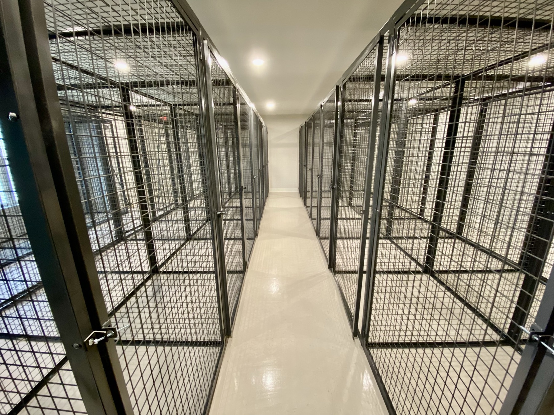
- Back Panels
- Returns & Dividers
- Tier Dividers
- Ceiling Panels
- Doors & Hardware
Illustrative 3′ × 3′ bays, 7′ 6″ high, shown with backs and ceilings. Display details remain subject to project review; this is not a fabrication drawing or installation sequence.
Specification Schedule
| Component | Standard / Typical | What To Confirm |
|---|---|---|
| Mesh | 10-gauge, 2″ × 2″ square welded wire | Other infill reviewed for the project |
| Angle Members | 1¼″ × 1¼″ × ⅛″ steel angle | Confirm the component-specific profile |
| Front Return | 2″ front vertical flat; angle at other edges | Shared dividers and end conditions vary |
| Back Return | Angle on all four sides | Used where the return arrangement requires it |
| Back Panel | Top/bottom angles; 2″ vertical flats | Required where no suitable existing wall closes the back |
| Nominal Height | 7′ 6″ | Custom heights reviewed from the layout |
| Nominal Widths | 3′, 4′, 5′, 6′ | Clear internal space and door opening vary |
| Nominal Depths | 3′, 4′, 5′ | Deeper/custom arrangements reviewed |
| Door Assembly | Prehung door in a four-sided frame; three spun-pin hinges | Handing and lock preparation selected for the project |
| Tier Arrangement | Single full-height or two stacked compartments | Specify compartment count separately from bay count |
| Standard Paint | Battleship Gray or Jet Black electrostatic enamel | Powder coat, galvanizing, or combined finish reviewed |
These are nominal product details, not fabrication cut sizes. Your quote and approved drawings identify the actual dimensions, infill, finish, closures, accessories, and hardware.
Wire Mesh & Welded Construction
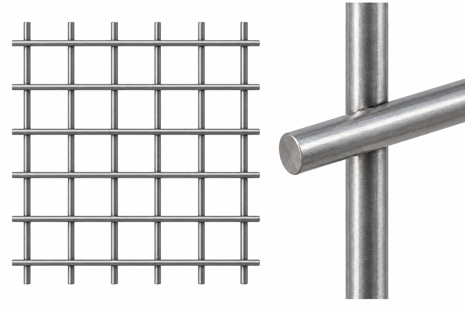
Standard ProGuard tenant lockers use 10-gauge wire with a 2″ × 2″ square welded pattern. There are two different weld relationships to understand: the intersections within the mesh, and the attachment of that mesh to its steel frame.
Welded Wire Close-Up
Inside The Angle Frame
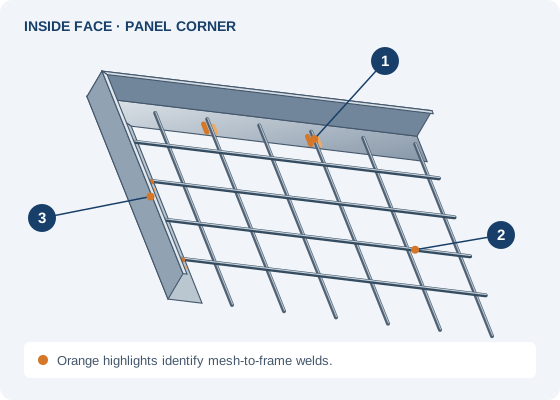
01 / Mesh-To-Frame Weld
The wire mesh lies against the flat leg of the angle. Welds secure the mesh to that supporting steel surface, tying the infill to the surrounding frame. The orange marks in the detail identify these attachment locations.
02 / Overlapping Wire Layers
Horizontal and vertical wires stay straight. One direction sits over the other, and the wires are welded at the crossings. This is square welded mesh; it is not a woven or lockcrimp pattern.
03 / Inside Angle Leg
The second leg of the angle projects into the locker. This gives the perimeter its L-shaped section and leaves the mesh supported along the frame. The close-up shows the inside of the panel.
The enlarged illustration explains the construction relationship. Highlighted weld locations are illustrative, not a weld-size or spacing schedule. Final fabrication follows the approved product and project details.
Choosing Another Infill
Selected woven-wire patterns, heavier wire, expanded metal, and sheet-steel infill may be reviewed for a project. Start with the opening size, visibility, separation, and finish requirements. Changing infill can affect the frame and overall assembly; confirm the complete combination with NWW.
Framing & Panel Connections
Standard angle members are 1¼″ × 1¼″ × ⅛″ steel. Each component has a specific framing arrangement. A return, back panel, and door are not interchangeable four-sided boxes.
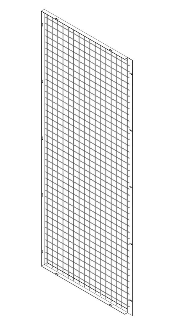
Front Return
A 2-inch vertical flat sits at the aisle-facing edge between the door frames. The top, bottom, and rear use angle. These panels form the sides and shared dividers at the front of a run.
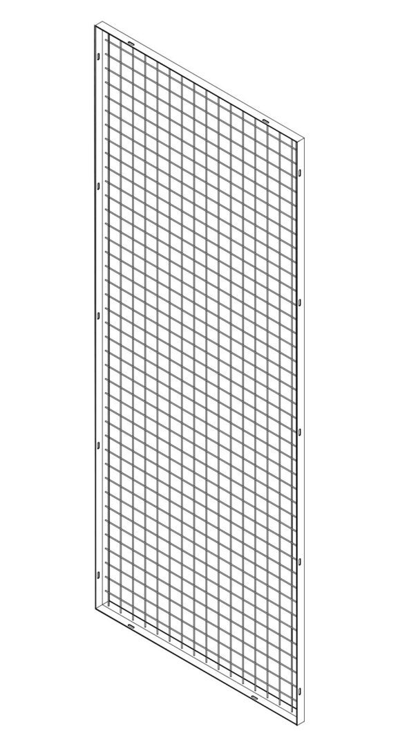
Back Return
Deeper arrangements can continue with a back return. It uses angle on all four sides and joins the front return angle-to-angle. It does not have a second front-edge flat.
Back Panels Are Different From Back Returns
A back panel closes the rear of the locker. It uses top and bottom angle members and 2-inch vertical flats. Adjacent back-panel flats overlap at the connection; the final overlap and fastening detail are coordinated for the approved layout.
Slotted Connections & Hardware
Slotted framing connections give the assembly its mounting locations. The NWW construction model uses carriage-bolt and KEP-nut connections. The domed head, square neck, threaded shank, and nut are separate physical parts in the new 3D view.
Panel slots and door hardware preparation serve different purposes. Return-panel mounting slots are not a blanket instruction to punch the door leaves. Fastener length and joint grip follow the actual combination of members.
Doors, Hinges & Access
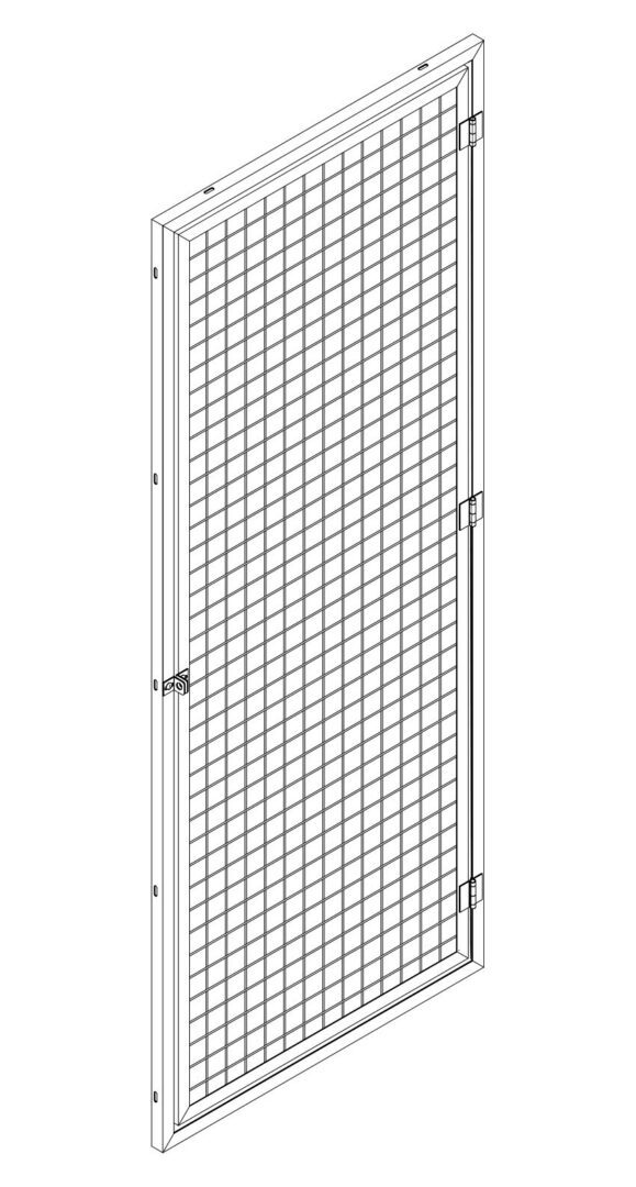
The Door Is Its Own Assembly
A moving angle-framed mesh leaf sits within a fixed four-sided door frame, or buck. Three spun-pin hinges support each door. The lock preparation and stops complete the access arrangement.
In a double-tier unit, upper and lower leaves operate separately. Each compartment has its own door and access point. The model separates the opening angles so both leaves remain visible.
Show The Handing On The Plan
Locate the hinges and latch relative to the aisle, room entrance, and adjacent doors. A door needs room to swing without blocking the route residents use to carry belongings.
The 3D demonstration uses a representative right-hinged arrangement. It is a visual explanation; final handing, clear opening, lock selection, and hardware positions belong on the approved drawings.
Finishes
Paint Finishes
Standard electrostatic enamel finishes are Battleship Gray and Jet Black. Ask about a project color when the lockers need to coordinate with the building.
Color swatches are illustrative. Use an approved physical sample for the final selection.
Powder Coat & Galvanizing
Powder Coat
Specify the desired color and service environment. Available colors and preparation are reviewed for the project.
Hot-Dip Galvanized
An option for compatible steel assemblies when the exposure calls for it. Tell us where the lockers will be installed.
Galvanized + Powder Coat
A combined finish can be reviewed with the required surface preparation, color, and coating specification. Confirm the complete process before ordering.
Layout & Accessories
Back Panels
An approved existing wall may close the rear of a run. Use back panels where there is no suitable wall or the lockers stand away from it.
Ceiling Panels
Close the top of the enclosure where the project calls for it. Coordinate overhead services and required access.
Shelves & Dividers
Double-tier units have separate upper and lower compartments. Additional shelving is reviewed for height, material, dimensions, and intended use.
Floor Panels
Discuss a floor panel when the project needs one. Record the existing floor condition and the belongings being stored.
Front Panels & Returns
Fixed infill closes the space beside a door. Returns establish the sides and depth; their arrangement changes at ends, corners, and offsets.
Locks & Door Handing
Select the locking arrangement and swing to suit management and resident access. Show handing on the layout before fabrication.
Starter And Add-On Layouts
A starter establishes the first complete locker opening. Add-on bays share adjoining dividers, so a row is not simply a collection of separate four-sided boxes. The final end, existing walls, corners, and changes in depth determine which returns and closures are needed.
Count the resident compartments you need, then let the NWW team review the components required to build the row. A double-tier bay provides two compartments, not two full-height lockers.
Drawings & Downloads
Send the building location, room plan, desired compartment count, finish, and timing with your request. A marked-up plan or measured sketch is enough to start the discussion.
Common Planning Questions
Can You Make Custom Sizes?
Yes. Custom widths, depths, heights, and mixed arrangements can be reviewed from your room layout. Standard nominal dimensions are a starting point; clear openings and usable space depend on the final construction.
Do All Lockers Need Back And Top Panels?
No. An approved existing wall may serve as the back. Tops, backs, and other closures depend on the arrangement and project requirements; identify them on the quote and drawings.
Can Single And Double Tiers Share A Room?
Yes. A mixed layout can accommodate different storage needs. Identify the compartment count and sizes so the shared panels, doors, and access can be coordinated.
What Should I Measure Before Asking For A Quote?
Record room lengths, usable height, entrances and swings, columns, pipes, ducts, equipment access, and changes in floor level. Photos help explain conditions a plan may not show.
Can The Layout Work Around Pipes Or Columns?
Show the obstruction location and size on the plan. NWW can review a suitable layout or project-specific detail; keep required service and maintenance access clear.
Start With Your Room
Have Plans? Send Them Over
A room plan, a sketch, or a few measurements gives our team a useful place to start.